The MakerBot Replicator
A look into the machine that brought FDM printing home
Read spotlight →Guiding questionWhy are different manufacturing techniques used for producing different products?
A design that cannot be made is not a design, it is a drawing. This topic exists to close the gap between those two things, and it is where a lot of ambitious ideas quietly get better. Once you know that a part has to release from a mould, or that an internal corner has a radius because the cutting tool is round, you start drawing differently. The constraint is not the enemy of the idea. It is usually what gives the idea a shape.
Learn the five categories properly rather than approximately, because Paper 2 rarely asks you to name a process. It asks you to choose one and defend the choice against volume, material, geometry, cost and finish, all at once, which is also exactly the reasoning your IA needs. The newer material here, particularly 4D and 5D printing, is genuinely unsettled. These are technologies still arguing with themselves about what they are for, which makes them unusually interesting to write about if you read beyond these notes.
Students must be able toOutline additive, subtractive (wasting), forming, joining and finishing techniques, relevant to the properties of the selected material(s).
All manufactured products result from applying one or more techniques drawn from five broad categories. The choice of category depends on material properties, desired geometry, production volume and cost.
| Category | Principle | Typical materials | Examples |
|---|---|---|---|
| Additive | Build up material layer by layer | Polymers, metals, ceramics, composites | SLA, FDM, SLS, material jetting |
| Subtractive | Remove material from a solid block | Metals, polymers, wood, composites | Turning, milling, laser cutting, waterjet |
| Forming | Reshape without adding or removing material | Metals, thermoplastics | Casting, injection moulding, rolling, forging |
| Joining | Fasten two or more parts permanently or temporarily | Any combination | Welding, soldering, adhesives, fasteners |
| Finishing | Protect or enhance the surface | Metals, polymers, wood | Anodising, powder coating, polishing |
The categories are not mutually exclusive; a single product typically requires techniques from several categories applied in sequence.
Additive manufacturing can build almost any geometry with no tooling cost, so in theory it should be replacing subtractive, forming and joining across the board. In practice, most mass-market products still aren't printed. A subtractively-machined aluminium part is stronger and cheaper than a printed one at high volume; an injection-moulded polymer part can be produced in seconds once the mould exists, where a printed equivalent takes hours.
For a product you use daily, work out which of the five categories actually made it, and why. What would have to change, materially, economically or technologically, before additive manufacturing became the default rather than the exception for that product?
Students must be able toExplain how components are produced using additive manufacturing techniques, including fused deposition modelling (FDM) and stereolithography (SLA).
Additive manufacturing (AM) constructs objects by depositing or curing material one cross-sectional layer at a time. Chuck Hull invented stereolithography in 1984, marking the birth of commercial 3D printing.
| Process | Material feedstock | Energy/mechanism | Strengths | Limitations |
|---|---|---|---|---|
| Stereolithography (SLA) | Liquid photopolymer resin | UV laser cures each layer | Very high accuracy; smooth surface finish | Brittle parts; post-cure required; resin cost |
| Fused Deposition Modelling (FDM) | Thermoplastic filament (PLA, ABS, PETG…) | Heated nozzle melts and deposits | Low cost; wide material choice; large build volumes | Visible layer lines; anisotropic strength |
| Selective Laser Sintering (SLS) | Polymer or metal powder | Laser sinters powder bed | No support structures needed; strong parts | Powder handling; surface porosity |
| Material Jetting | Photopolymer droplets | UV curing of inkjet-deposited drops | Multi-material; full colour; very high detail | High cost; brittle support material |
| Binder Jetting | Powder + liquid binder | Binder printed onto powder bed | High speed; large metal parts possible | Lower density; sintering step required |
| Directed Energy Deposition (DED) | Metal wire or powder | Laser or electron beam melts feedstock in flight | Repairs and additions to existing parts | Rough surface; expensive equipment |
A material is isotropic if its mechanical properties, such as strength and stiffness, are the same in every direction. It is anisotropic if those properties vary depending on the direction in which a load is applied. FDM parts are anisotropic because each layer bonds well within itself but only partially fuses to the layer above it, so the part is weaker when pulled apart along the layer lines (the Z-axis) than when loaded in the X-Y plane.
This connects to the discussion of material properties in A3.1 Material Classification: most bulk metals and polymers are treated as isotropic, but processes that build a part from oriented layers, fibres or grains (3D printing, composite lay-up, wood grain, rolled sheet metal) introduce direction-dependent behaviour that a designer must account for when orienting a part for printing or loading.
A look into the machine that brought FDM printing home
Read spotlight →Students must be able toDistinguish between rapid prototyping techniques used for creating initial base models (which serve as a foundation for testing and validation) as opposed to techniques used in the production of refined products.
Rapid prototyping (RP) is the fast production of a physical model directly from CAD data, used primarily for form, fit and function testing early in the design process.
Workflow: CAD model → export as STL/3MF → slice into layers → print → post-process → evaluate
| Characteristic | Rapid prototype | Production part |
|---|---|---|
| Purpose | Test geometry, ergonomics, assembly | End-use function |
| Material | Cheap polymer (PLA, resin) | Specified engineering material |
| Volume | 1–5 units | 100s–millions |
| Finish | Often rough / support marks | Meeting spec tolerances |
| Lead time | Hours to days | Days to weeks per mould/setup |
| Cost per part | Higher (no tooling amortisation) | Lower at scale |
As AM materials and accuracy improve, the boundary between prototype and production part blurs. GE Aviation now produces certified LEAP engine fuel nozzles using SLS.
Students must be able toDescribe additive manufacturing techniques used in manufacturing, including powder bed fusion (PBF), material extrusion, and selective laser sintering (SLS).
AM is particularly suited to low-volume, high-complexity, or patient-specific production where conventional tooling would be prohibitively expensive. The crossover point where injection moulding becomes cheaper than AM is typically around 1,000–10,000 units depending on part complexity.
| Industry | Application | AM process | Benefit |
|---|---|---|---|
| Medical/Dental | Invisalign aligners; patient-specific implants | SLA, SLS, material jetting | Mass customisation; no tooling per patient |
| Aerospace | GE LEAP fuel nozzles; Airbus bracket | SLS (Ti-6Al-4V) | Weight reduction; consolidated parts |
| Automotive | F1 brake ducts; Bugatti titanium caliper | SLS metal | Complex topology-optimised geometry |
| Consumer goods | Adidas 4D midsole; New Balance FuelCell | DLP/SLA lattice | Tunable cushioning; on-demand production |
| Construction | ICON concrete 3D-printed homes (Texas) | Concrete extrusion (DED variant) | Reduced labour; complex geometry possible |
Students must be able toExplain how the use of shape memory polymers can be deployed for printing 4D objects and provide examples of their potential use.
4D printing (coined by MIT's Skylar Tibbits, 2013) is 3D printing with smart materials: the fourth dimension is time, representing the transformation that occurs after printing.
Key smart materials:
Four-stage SMP cycle:
| Application area | Example | Stimulus |
|---|---|---|
| Biomedical | Self-deploying stents; drug delivery capsules | Body heat |
| Aerospace | Morphing aerofoils; deployable solar panels | Temperature |
| Soft robotics | Gripper fingers that curl around objects | Temperature / humidity |
| Smart textiles | Self-adjusting sportswear ventilation | Moisture / heat |
Students must be able toExplain how 5D technology can be used to produce long-lasting and complex components in biomedical, automobile and aerospace applications.
Standard 3D printing moves in three axes (X, Y, Z). 5D additive manufacturing adds two rotational axes (one on the extruder head and one on the print bed), allowing the nozzle to deposit material on curved surfaces from multiple angles.
Key advantages over 3D printing:
| Industry | Application | 5D benefit |
|---|---|---|
| Biomedical | Skull implants; bone scaffolds | Curved surfaces match anatomy; no support contamination |
| Automotive | Structural brackets; B-pillar inserts | Fibre orientation matches load paths; weight saving |
| Aerospace | Turbine blade coatings; fuselage ribs | Complex curvature; high-strength composite deposition |
Students must be able toExplain how components are produced using wasting manufacturing techniques, including machining (cutting, milling, turning) and abrading processes, which are applied to both 3D and 2D materials.
Subtractive (wasting) processes begin with a solid block or sheet and remove material to reveal the final shape. CNC (computer numerical control) automation allows extremely precise, repeatable cuts.
| Process | Mechanism | Materials | Typical application |
|---|---|---|---|
| Turning (lathe) | Workpiece rotates; cutting tool traverses | Metals, polymers, wood | Shafts, cylinders, threads |
| Milling | Rotating cutter moves across stationary workpiece | Metals, polymers, composites | Flat surfaces, slots, pockets, complex 3D profiles (5-axis) |
| EDM / Wire cutting | Electrical discharge erodes metal | Conductive metals | Hardened tool steel dies; very fine features |
| Laser cutting | Focused laser melts/vaporises material | Sheet metal, polymers, wood, fabrics | 2D profiles; thin materials |
| Plasma cutting | Ionised gas jet melts and blows away metal | Conductive metals (up to 150 mm) | Structural steel; shipbuilding |
| Abrasive waterjet | Water at 280–690 MPa + abrasive grit | Any material including stone, glass, titanium | Heat-sensitive or hard materials |
Subtractive processes produce excellent surface finishes and tight tolerances (±0.01 mm or better for CNC milling), but can generate significant material waste (swarf/chips).
CNC describes any manufacturing machine, a lathe, mill, router, laser or plasma cutter, that is guided by a computer program rather than a human operator moving the tool by hand. The designer's CAD model is converted into G-code, a list of coordinate and tool instructions, which drives motors to move the cutting tool along the programmed path with repeatable accuracy measured in microns.
This builds on the prototyping workflow introduced in A2.2 Prototyping Techniques: where a 3D printer deposits material to build a part, a CNC machine removes it, and both rely on the same digital file, the CAD model, to translate a design directly into a physical object without dedicated tooling for each one-off part.
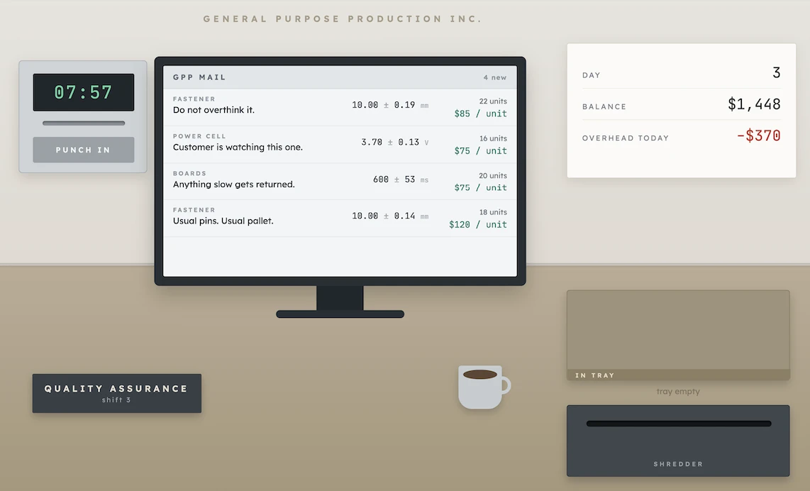
Measure products, test batteries, and pretend to have fun in this thrilling and somewhat stressful game.
Students must be able toExplain how components are produced using forming techniques, including bending, press-forming, casting, moulding (injection, extrusion, rotational, blow, vacuum) processes.
Forming exploits a material's plasticity, fluidity (molten) or elasticity. Since material is not wasted, forming is generally more material-efficient than subtractive methods.
Metal casting:
| Process | Mould type | Notes |
|---|---|---|
| Sand casting | Expendable sand mould | Low tooling cost; rough surface; any alloy |
| Investment (lost-wax) casting | Expendable ceramic shell | Excellent detail and surface; complex 3D shapes; expensive |
| Die casting | Permanent steel die | High volume; thin walls; aluminium/zinc alloys |
| Continuous casting | Water-cooled copper mould | Junghans process (1933); molten steel solidifies as a strand; standard for steel/aluminium production |
Polymer moulding:
| Process | Principle | Typical products |
|---|---|---|
| Injection moulding | Molten polymer injected into closed mould under pressure | Phone cases, bottle caps, dashboard parts |
| Blow moulding | Hollow parison inflated inside mould | PET bottles, fuel tanks |
| Thermoforming | Sheet heated then vacuum- or pressure-formed over tool | Food packaging, bathtubs, aircraft cabin panels |
| Extrusion | Polymer forced through a die; continuous profile | Pipe, window frames, cable insulation |
| Rotational moulding | Powder loaded into mould; mould heated and biaxially rotated | Large hollow items: tanks, kayaks, playground equipment |
Students must be able toExplain how components are assembled using joining techniques, including adhering, fastening, stitching, weaving and welding processes.
Joining creates assemblies from separate components. The choice between permanent and temporary joining has significant implications for repairability, recycling and end-of-life disassembly.
| Technique | Type | Mechanism | Example / notes |
|---|---|---|---|
| Fusion welding | Permanent | Base metal melted; may use filler rod (MIG, TIG, arc) | Steel structures, pipelines |
| Solid-state welding | Permanent | No melting: friction stir, ultrasonic, explosive | Dissimilar metals; aircraft fuselage panels |
| Soldering | Permanent | Filler alloy melted below 450 °C; wets parent metals | PCB assembly (SAC305 lead-free solder per RoHS) |
| Brazing | Permanent | Filler alloy melted above 450 °C; base metals not melted | Copper pipe joints; tool tips |
| Adhesives | Permanent | Chemical bonding at surface (epoxy, cyanoacrylate, structural acrylic) | Aerospace composite bonds; automotive body panels |
| SMT (Surface Mount Technology) | Permanent | Solder paste + reflow oven attaches SMD components to PCB | All modern PCBs; very high component density |
| Mechanical fasteners | Temporary | Bolts, screws, rivets, snap-fits, press-fits | Wide use; allows disassembly |
| Stitching / weaving | Permanent / temporary | Thread or fibre interlocks | Textiles; fibre-reinforced composites (woven prepreg) |
One cam, one dowel, and the flat-pack industry it built.
Read case study →Students must be able toSuggest how natural and human-made finishing techniques (anodising, electroplating, galvanising), coatings (powder coating), polishing, and sealants enhance a product's aesthetics, protection, durability, longevity and ease of maintenance.
Finishing techniques are applied after forming or machining to alter the surface chemistry, texture or appearance of a component. They can dramatically extend product life and perceived quality.
| Technique | Process | Material | Benefit | Examples |
|---|---|---|---|---|
| Anodising | Electrochemical: aluminium becomes anode in sulphuric acid bath; oxide layer grows into surface | Aluminium alloys | Corrosion resistance; hard surface; accepts dyes | iPhone enclosures; bicycle frames; architectural cladding |
| Electroplating | DC current deposits metal ions (chrome, nickel, gold, silver) from solution onto workpiece (cathode) | Any conductive substrate | Decorative; corrosion / wear resistance; conductivity | Chrome taps; gold-plated connectors; nickel-plated steel |
| Hot-dip galvanising | Steel immersed in molten zinc (450 °C); zinc-iron alloy layers bond; surface shows characteristic spangle | Steel | Sacrificial cathodic protection; very thick coating | Street furniture, motorway barriers, structural steelwork |
| Powder coating | Dry polymer powder electrostatically applied then cured at 177–204 °C in oven | Metals | Thick, even coat; no VOC solvents; wide colour range | Garden furniture, bicycle frames, kitchen appliances |
| Ceramic coating | Silicon dioxide (SiO₂) or titanium dioxide (TiO₂) nano-layer applied and cured | Metals, glass, polymers | Extreme hardness; UV and chemical resistance; hydrophobic | Automotive paintwork protection; cookware; aerospace |
| Polishing | Abrasive or chemical removal of surface peaks; electropolishing uses electrochemical dissolution | Metals, polymers, glass | Improved aesthetics; reduced friction and bacterial adhesion | Surgical instruments; optical components; jewellery |
Students must be able toSuggest why specific manufacturing techniques have been used to create a given component.
No real product uses only one category of technique. The design team must reason about why each technique is selected by connecting material properties, geometry, volume, cost and sustainability.
Case study (smartphone, iPhone-type aluminium body):
| Component | Technique(s) | Category | Rationale |
|---|---|---|---|
| Aluminium enclosure | CNC milling from billet + anodising | Subtractive + Finishing | Billet milling gives tight tolerance and complex radii; anodising provides colour, scratch resistance and eliminates paint |
| Glass back panel | Chemical strengthening (ion exchange) + polishing | Forming + Finishing | Ion exchange compresses surface for crack resistance; polishing ensures optical clarity |
| PCB | SMT reflow soldering | Joining | Enables placement of hundreds of components in mm²; no through-holes required |
| SoC (chip) | Photolithography (subtractive at nm scale) + wire bonding | Subtractive + Joining | Transistors defined by etching; die bonded to substrate |
| Battery | Winding / stacking of electrodes + laser welding | Forming + Joining | Electrode layers formed by calendering; sealed by laser welding |
| Camera lens | Glass pressing + polishing + anti-reflection coating | Forming + Finishing | Precision pressing gives lens shape; polishing and coating ensure optical performance |
Exam tip: when asked to "suggest why," link the technique to a specific material property or product requirement (e.g., "injection moulding is used for the polymer casing because the high-volume production run amortises the tooling cost").
Ten questions covering the learning objectives for this topic. Select one answer per question, then click "Check all answers" to see your score and the explanations.
A jet engine turbine blade runs in gas at 1500 °C while spinning fast enough to load it with several tonnes of centrifugal force. It is a complex curved form with cooling passages running through its interior.
It is made by investment casting. A wax pattern is made, coated in ceramic slurry to build a shell, the wax is melted out, molten alloy is poured in, the shell is broken away, and the root is then machined to its final dimensions.
Table 1: Stages in blade manufacture
| Stage | Process | Category |
|---|---|---|
| 1 | Wax pattern injected into a die | Forming |
| 2 | Ceramic shell built by repeated dipping | Forming |
| 3 | Wax melted out, alloy poured | Casting |
| 4 | Shell broken away | — |
| 5 | Root machined on a 5-axis mill | Subtractive |
| 6 | Thermal barrier coating applied | Finishing |
(a) State the category of manufacturing technique used at stage 3, see Table 1. [1]
(b) Outline why the internal cooling passages cannot be produced by machining, see Table 1. [2]
(c) Explain why the root is machined after casting rather than cast to its final size, see Table 1. [3]
(a) Casting.
(b) A cutting tool has to reach the surface it is cutting, and a passage that runs through the interior of a curved blade has no straight line of access from outside. Casting produces the passage instead by forming the metal around a ceramic core that is dissolved out afterwards, so the shape is defined by what was there rather than by what was removed.
(c) Casting cannot hold the tolerance the root needs. The alloy shrinks as it solidifies and cools, and the ceramic shell moves slightly during firing and pouring, so a cast surface is accurate to a few tenths of a millimetre at best. The root is the feature that locates the blade in the disc and transfers several tonnes of centrifugal load into it, so its fit determines how that load is distributed, and a poor fit concentrates stress and cracks the disc. The surface finish matters for the same reason, because a rough cast surface leaves marks that act as crack initiation sites in a component under high cyclic load. Machining is the only process that reaches the accuracy and finish required, so the blade is cast slightly oversize at the root and the last fraction of a millimetre is cut away. It is done in this order because machining the whole blade would be prohibitively slow and wasteful, so casting is used for the complex form and machining is confined to the one surface that must be precise.
(a) Manufacturing techniques can be organized into five categories.
• Casting ✓
Award [1] for the correct category up to [1 max].
(b) Subtractive techniques remove material from a solid block to achieve the desired shape.
• A cutting tool must physically reach the surface it cuts ✓
• An internal passage inside a curved blade has no straight line of access ✓
• The tool would have to pass through solid material to reach the cavity ✓
• Casting forms the metal around a ceramic core that is dissolved out afterwards ✓
• The shape is defined by what was there rather than by what was removed ✓
• The passages follow curved paths that no straight tool could produce ✓
• Chips and coolant could not be cleared from an enclosed cavity ✓
Award [1] for each relevant brief point on why machining cannot produce the passages up to [2 max].
(c) Manufacturing techniques are selected according to the accuracy, finish and complexity required.
• Casting cannot hold the tolerance the root requires ✓
• The alloy shrinks as it solidifies and cools ✓
• The ceramic shell moves slightly during firing and pouring ✓
• A cast surface is accurate to a few tenths of a millimetre at best ✓
• The root locates the blade in the disc and transfers several tonnes of load ✓
• Fit determines how that load is distributed across the root ✓
• A poor fit concentrates stress and can crack the disc ✓
• A rough cast surface leaves marks that initiate cracks under cyclic load ✓
• Machining is the only process reaching the required accuracy and finish ✓
• The blade is cast oversize at the root and the last fraction cut away ✓
• Machining the whole blade would be prohibitively slow and wasteful ✓
• Casting handles the complex form; machining is confined to the surface that must be precise ✓
Award [1] for each relevant reason / cause explaining why the root is machined after casting up to [3 max]. Award a maximum of [2] where the response does not identify the function of the root.
A bicycle frame is a set of tubes joined into a triangulated structure. Three methods of joining are in use.
Table 2: Three frame joining methods
| TIG welding | Brazing into lugs | Bonding into lugs | |
|---|---|---|---|
| Materials suited | Steel, aluminium, titanium | Steel | Carbon composite |
| Joint temperature | Above tube melting point, locally | Below tube melting point | Ambient to 120 °C |
| Filler | Same alloy as tube | Brass or silver alloy | Epoxy adhesive |
| Heat affected zone | Present, may need heat treatment | Smaller | None |
| Repairable | Yes | Yes, tube replaceable | Difficult |
| Suits mass production | Yes | Slow | Yes |
(a) State the category of manufacturing technique to which all three methods in Table 2 belong. [1]
(b) Describe why brazing produces a smaller heat affected zone than TIG welding, see Table 2. [2]
(c) Justify the selection of a joining method for a small workshop building steel frames to individual customer measurements, see Table 2. [3]
(a) Joining.
(b) Brazing melts only the filler alloy, which flows into the joint at a temperature below the melting point of the tube, so the steel itself is never taken to melting. Because less heat enters the tube and it is spread through the lug, a smaller volume of the parent metal is heated far enough for its microstructure to change.
(c) Brazing into lugs is the right selection for this workshop. Building to individual measurements means every frame has different tube lengths and joint angles, and lugs accommodate that within their designed range while holding the tubes in alignment during the joint, which does much of the work a jig would otherwise have to do for a one-off frame. The lower heat input matters because it distorts the frame less, and a frame built to a customer's measurements has to end up at those measurements, so pulling out of alignment during welding is a real cost when there is only one of them. Brazing also lets a single damaged tube be unsoldered and replaced rather than the frame being scrapped, which suits an expensive made-to-measure product the customer expects to keep for decades. The usual objection, that brazing is slow, does not apply here: a workshop building one frame at a time is not competing on throughput, and the labour is already the dominant cost. TIG welding would be faster and is the correct choice at volume, but it demands accurate mitred tube ends and jigging that a small workshop would have to set up afresh for every frame.
(a) • Joining ✓
Award [1] for the correct category up to [1 max].
(b) Joining techniques can permanently or temporarily join similar or dissimilar materials.
• Brazing melts only the filler alloy, not the tube ✓
• The filler flows into the joint below the tube's melting point ✓
• The steel is never taken to melting ✓
• Less heat enters the tube overall ✓
• The lug spreads the heat over a larger area ✓
• A smaller volume of parent metal reaches the temperature at which microstructure changes ✓
• TIG melts the tube itself, so the parent metal is heated well beyond its melting point locally ✓
Award [1] for each detail, leading to an account of the smaller heat affected zone, up to [2 max].
(c) Various factors influence the choice of manufacturing techniques, including scale of production and the accuracy required.
Credit a justified selection. Indicative content for brazing into lugs:
• Every frame has different tube lengths and joint angles ✓
• Lugs accommodate variation within their designed angle range ✓
• Lugs hold the tubes in alignment during the joint, doing the work of a jig ✓
• A one-off frame cannot justify building a dedicated jig ✓
• Lower heat input distorts the frame less ✓
• A made-to-measure frame must finish at the customer's measurements ✓
• A single damaged tube can be unsoldered and replaced rather than the frame scrapped ✓
• Repairability suits an expensive product kept for decades ✓
• The slowness objection does not apply, since the workshop is not competing on throughput ✓
• Labour is already the dominant cost in a bespoke frame ✓
Indicative content for TIG:
• Faster, and suits any steel, aluminium or titanium tubing ✓
• No lug inventory to hold for every angle combination ✓
• Not restricted to the angles available in stock lugs ✓
• Requires accurate mitred tube ends and jigging set up for each frame ✓
Award [1] for each valid reason / piece of evidence justifying the selection up to [3 max]. Credit either selection provided it is justified against the small workshop and made-to-measure context.
A vacuum flask keeps a drink hot for twelve hours. It is a stainless steel bottle within a bottle, joined at the neck, with the air between the two walls evacuated so that heat cannot cross by conduction or convection.
Each wall starts as a flat steel disc.
(a) List two forming techniques that could produce one of the flask’s seamless walls from a flat steel disc. [2]
Table 3: Manufacturing sequence for the flask body
| Stage | Process | Purpose |
|---|---|---|
| 1 | Deep drawing, four stages | Form each wall from a disc |
| 2 | Annealing between draws | Restore ductility |
| 3 | Laser welding at the neck | Join inner to outer wall |
| 4 | Evacuation through a port, port sealed | Remove air from the cavity |
| 5 | Electropolishing of the inner surface | Smooth finish, no taste transfer |
| 6 | Powder coating of the outer surface | Colour and grip |
(b) Outline why annealing is required between the drawing stages, see Table 3. [2]
The two walls are joined by laser welding at the neck, a ring weld a few millimetres wide. Any leak in that weld admits air and the flask stops working.
(c) Describe why laser welding is selected for this joint rather than TIG welding, see Table 3. [2]
A start-up proposes producing the flask body by metal additive manufacturing instead, printing the double wall as a single part with the cavity already enclosed.
(d) Evaluate the proposal to produce the flask body by additive manufacturing, see Table 3. [4]
(a) Deep drawing, and metal spinning.
(b) Drawing deforms the steel plastically, and each draw work hardens it further, so the metal becomes progressively stronger and less ductile until it would tear on the next stage. Annealing heats it enough to recrystallise the grain structure, which restores ductility and lets the next draw take place.
(c) The weld has to be vacuum tight and it sits a few millimetres from a thin wall, so the heat has to be confined. A laser puts a narrow, precisely placed beam into a very small volume, which produces a continuous seam without distorting the neck or transmitting enough heat to affect the polished inner surface. TIG delivers heat over a much wider area and would distort thin steel and enlarge the heat affected zone, and it is also slower and harder to automate for a ring weld repeated at production volume.
(d) The proposal is attractive in principle and weak against this particular product.
Its genuine advantage is that it eliminates the joint. The neck weld is the flask's critical failure point, since any leak destroys the vacuum, and a printed part with the cavity already enclosed has no weld to fail. It would also collapse a six stage sequence into one operation and allow geometries that drawing cannot produce, such as an internal lattice or a non-circular section.
Against that, the cavity has to be enclosed and unreachable, which is exactly what makes printing it hard. Powder bed processes leave unfused powder inside every closed cavity, and there is no way to remove it from a sealed one, so the flask would be full of loose steel powder in the space that must be empty. That is not a detail to solve later, it is the central conflict between the process and the product.
Surface finish is the second objection. A printed surface is rough and would need machining or polishing to meet the taste and hygiene requirement of stage 5, and the inner surface of a deep narrow bottle is the hardest surface to reach. Drawing delivers a smooth surface directly off the tool.
Cost is decisive at volume. Deep drawing produces a wall in seconds against hours for a printed one, and the die cost is amortised across millions of units, so printing would raise the unit cost of a commodity product by an order of magnitude for no benefit the customer can perceive.
The proposal should not proceed for volume production. Additive manufacturing suits low volumes of geometrically complex parts, and a vacuum flask is a high volume part of simple geometry whose difficulty lies in the vacuum rather than the shape. It would earn its place in prototyping a new flask profile, where one body is needed quickly and no die exists.
(a) Forming techniques reshape material without adding or removing any of it.
• Deep drawing ✓
• Metal spinning ✓
• Hydroforming ✓
• Impact extrusion ✓
• Press forming ✓
Award [1] for each relevant forming technique up to [2 max]. Do not credit rolling and welding a seam, which does not produce a seamless wall.
(b) Forming techniques reshape material without adding or removing any of it.
• Drawing deforms the steel plastically ✓
• Each draw work hardens the metal further ✓
• The steel becomes progressively stronger and less ductile ✓
• Without annealing it would tear or split on the next stage ✓
• Annealing heats the steel enough to recrystallise the grain structure ✓
• Ductility is restored so the next draw can take place ✓
• It also relieves residual stresses that would distort the part ✓
Award [1] for each relevant brief point on why annealing is required up to [2 max].
(c) Joining techniques can permanently or temporarily join similar or dissimilar materials.
• The weld must be vacuum tight, so the seam must be continuous and defect free ✓
• It sits a few millimetres from a thin wall, so heat must be confined ✓
• A laser puts a narrow beam into a very small volume ✓
• The neck is not distorted and the polished inner surface is unaffected ✓
• TIG delivers heat over a much wider area ✓
• Wider heat input would distort thin steel and enlarge the heat affected zone ✓
• Laser welding is faster and easier to automate for a repeated ring weld ✓
• No filler is required, so nothing is introduced into the cavity ✓
Award [1] for each detail, leading to an account of why laser welding is selected, up to [2 max].
(d) Additive manufacturing builds objects layer by layer and is used for low-volume production runs.
Strengths:
• Eliminates the neck weld, which is the flask's critical failure point ✓
• Any leak destroys the vacuum, so removing the joint removes the main risk ✓
• Collapses a six stage sequence into one operation ✓
• No dies, presses or annealing furnaces required ✓
• Allows geometries drawing cannot produce, such as internal lattices or non-circular sections ✓
• Design changes need no new tooling ✓
Limitations:
• Powder bed processes leave unfused powder in every closed cavity ✓
• A sealed cavity cannot be cleared, so the flask would contain loose steel powder ✓
• That is the central conflict between the process and the product ✓
• A printed surface is rough and needs machining or polishing to meet stage 5 ✓
• The inner surface of a deep narrow bottle is the hardest to reach for finishing ✓
• Drawing delivers a smooth surface directly off the tool ✓
• Drawing forms a wall in seconds against hours for printing ✓
• Die cost is amortised across millions of units ✓
• Unit cost would rise by an order of magnitude for no perceptible customer benefit ✓
Judgment:
• Should not proceed for volume production ✓
• Additive suits low volumes of geometrically complex parts ✓
• A flask is a high volume part of simple geometry whose difficulty is the vacuum, not the shape ✓
• It would suit prototyping a new profile where no die exists ✓
Award [1] for each distinct strength / limitation, leading to an appraisal of the proposal, up to [4 max]. Award a maximum of [3] where only strengths or only limitations are given. Credit responses that identify the trapped powder problem.
Linking Questions
MakerBot's Replicator, launched in 2012, was many people's first encounter with a 3D printer that wasn't behind a lab door. Founded three years earlier in a Brooklyn hackerspace, MakerBot built its early machines directly on RepRap, an open-source project aiming to build a 3D printer that could print most of its own parts. The Replicator took that hobbyist hardware and packaged it as a roughly two-thousand-dollar desktop appliance, dual extruders included, right as the wider public was starting to hear the words "3D printing" for the first time.
Under the plastic shell, the machine works exactly as described above. A heated nozzle melts thermoplastic filament and deposits it one layer at a time, following the instructs provided by the gcode file. Look closely at anything printed on one and the anisotropy is visible directly.
In 1956, an IKEA employee named Gillis Lundgren struggled to fit a wooden table into his car and had the idea that started flat-pack furniture: unscrew the legs, and the same table takes a fraction of the space. That single insight turned joining technique into a shipping strategy. If a product could be joined by the customer instead of the factory, it could travel disassembled, stacked flat in a shipping container at a density solid furniture never achieves.
The joint that makes it work at IKEA's scale is the cam lock: a barrel-shaped cam sits in one panel, a dowel or screw sits in the other, and turning the cam with nothing more than a coin or the supplied hex key pulls the two panels together and locks them tight. It's a mechanical fastener exactly as described above, chosen specifically because it needs no glue, no welding equipment and almost no skill, and because it's fully reversible: the same joint that assembles a wardrobe in an apartment can be undone just as easily when it's time to move house or take it apart for recycling.