iFixit's Repairability Score
Turning "how hard is this to take apart" into a number manufacturers can't ignore.
Read case study →Guiding questionHow can the evolution of production systems transform the way products are designed and manufactured, and transform the efficient disposal of products?
DfM is where this course stops treating manufacture as something that happens to a design after it is finished. Every choice you make on a drawing has already committed somebody on a factory floor to a set of operations, a set of tools and a number of minutes per unit. A design that ignores this gets redesigned by the manufacturer, badly, without you.
Design for disassembly is the strategy worth caring about most and the one most often skipped. Design for process and design for assembly both pay off immediately in cost, so industry adopts them readily. Disassembly pays off at the end of a product's life, to somebody who is not the manufacturer, which is exactly why so many products are glued shut. That makes it the strategy where a designer's values show most clearly, and it links this topic straight back to C2.2 and C3.2. If you want a concrete way into this material, take something apart and count how many operations and how many separate materials stand between you and the battery.
A brilliant product that cannot be efficiently manufactured, assembled, repaired, or recycled is not a finished design: it is an expensive problem. Design for Manufacture (DfM) is the discipline of engineering manufacturability into a product from the very first sketch, ensuring that good design intentions survive contact with the factory floor, the repair bench, and the recycling facility.
DfM comprises three complementary strategies: Design for Process (optimising how a product is made), Design for Assembly (minimising assembly time and error), and Design for Disassembly (enabling repair, reuse, and recycling at end of life). Together these three strategies connect C4.1 to almost every other topic in the curriculum: from material selection to LCA to production systems.
Students must be able toOutline design for process, design for assembly and design for disassembly strategies.
Design for Manufacture (DfM) integrates manufacturing considerations into the earliest stages of product design. It is far cheaper to fix a manufacturing problem during the design phase than after tooling is built or production has started.
| Strategy | Focus | Key goal | Life-cycle phase |
|---|---|---|---|
| Design for Process (DfP) | How individual components are made | Reduce energy, waste, processes, and emissions during manufacturing | Production |
| Design for Assembly (DFA) | How components are joined into a product | Minimise part count; maximise assembly efficiency and error-prevention | Assembly |
| Design for Disassembly (DFD) | How components are separated at end of life | Enable repair, reuse, remanufacture, and recycling | End of life |
These three strategies are complementary but can sometimes conflict: a choice that optimises assembly (e.g., adhesive bonding) may hinder disassembly. Holistic DfM requires designers to balance all three throughout the design process.
Manufacturers may formalise DfM through quality management systems (ISO 9001) and environmental management systems (ISO 14001) to ensure consistent, measurable outcomes.
Students must be able toOutline the advantages of design for process and explain how a product could be designed using this strategy.
Design for Process (DfP) focuses on reducing the energy, material, processes, waste, and emissions involved in manufacturing individual components. Designers must understand the constraints and opportunities of each manufacturing process and design components that exploit process strengths.
DfP design guidelines:
Case study (Apple Unibody MacBook): The laptop body is CNC-machined from a single solid block of aluminium ("unibody"). This eliminates the need to join or weld multiple body parts together. Results: stronger and more rigid structure than multi-part assembly; finer tolerances; smooth, seamless finish; reduced assembly complexity. The trade-off: CNC machining removes 30–50% of the aluminium billet as waste swarf, but this is recyclable.
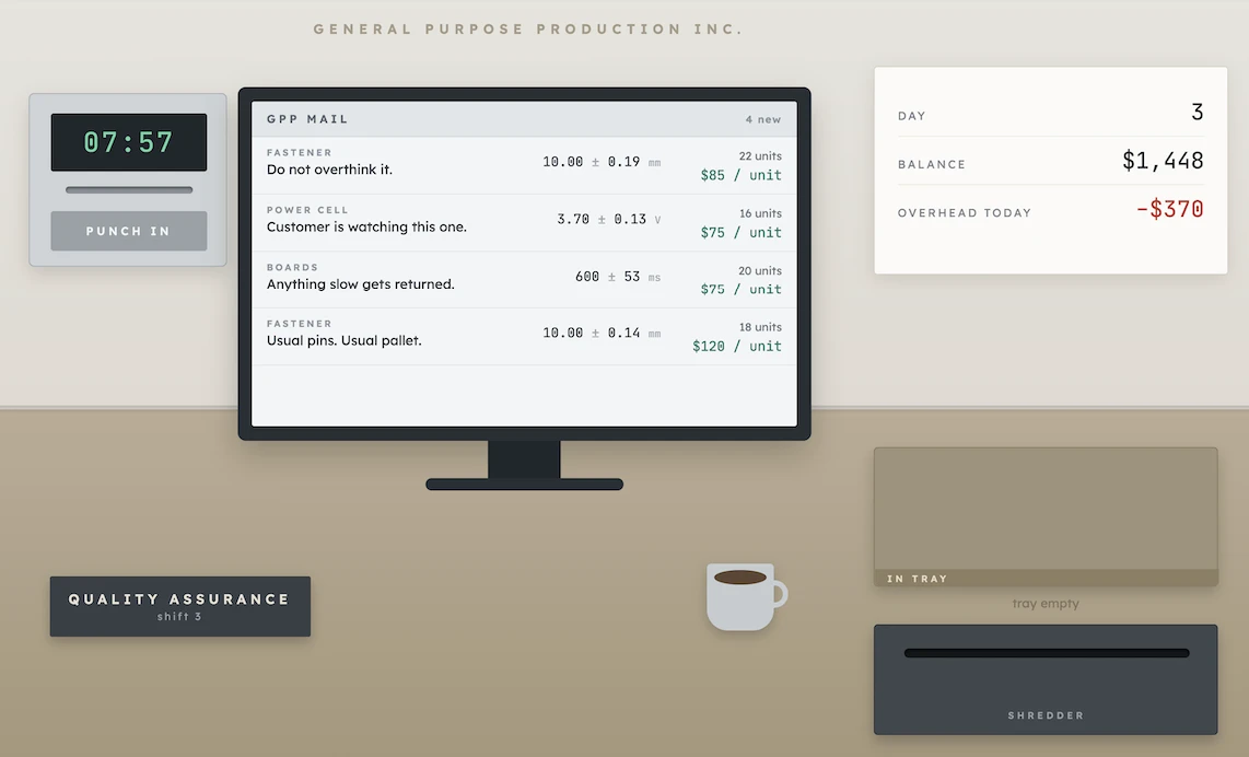
Measure products, test batteries, and pretend to have fun in this thrilling and somewhat stressful game.
Students must be able toOutline the advantages of design for assembly and explain how a product could be designed using the design for assembly strategy.
Design for Assembly (DFA) looks closely at how a product's components and sub-assemblies fit together, aiming to cut cost by trimming the part count and streamlining how efficiently the whole thing goes together. Fewer parts means faster assembly, smaller inventory, lower storage costs, and fewer potential failure points.
DFA principles:
| Principle | How to apply | Benefit |
|---|---|---|
| Reduce part count | Combine multiple components into single moulded or machined parts; eliminate redundant parts | Lower material cost; faster assembly; fewer failure points |
| Standardise fasteners | Use one screw size/type throughout; avoid custom fasteners | One tool needed; no mis-assembly risk from wrong fastener |
| Snap-fit and clip connections | Design press-fit or snap-fit joints that click into place without tools | Faster assembly; no fastener inventory; allows disassembly |
| Self-locating parts | Design parts that align themselves (symmetrical, keyed, or self-nesting) | Reduces jigs/fixtures; prevents mis-assembly; enables automation |
| Vertical axis of assembly | Design so all parts drop in from above; gravity assists alignment | Gravity-assisted; suits robotic assembly; faster cycle time |
| Modular design | Divide product into independent sub-assemblies that can be tested separately | Parallel assembly; easier repair/upgrade; mass customisation |
| Poka-Yoke (mistake-proofing) | Make incorrect assembly physically impossible (asymmetry, colour coding, keying) | Eliminates assembly errors; reduces rework and warranty claims |
Case study (Bosch circular saw redesign): Reduced from over 100 parts to dramatically fewer by combining components into single moulded parts, using snap-fit connections, self-locating symmetrical parts (preventing incorrect assembly), vertical axis of assembly (parts drop into place), and standard screws instead of custom fasteners.
Case study (IKEA furniture): Flat pack design minimises shipping volume; standardised cam-lock fasteners and dowels throughout the catalogue; symmetrical/reversible panels reduce assembly error; pictorial step-by-step instructions eliminate language barriers; modular units allow expansion and reconfiguration.
Poka-Yoke example (USB Type C, 2014): The connector is symmetrical: it can be inserted in either orientation. Previous connectors (USB-A, Micro-USB) were asymmetrical, causing frequent insertion errors. Symmetrical design prevents assembly errors entirely, speeds up manufacturing (robots don't need vision systems to detect orientation), and eliminates damage from forced insertion.
Students must be able toOutline the advantages of design for disassembly and explain how a product could be designed using this strategy.
Design for Disassembly (DFD) facilitates ease of repair, reuse, remanufacture, or recycling. It has become increasingly important as manufacturers must comply with WEEE (Waste from Electrical and Electronic Equipment) and RoHS (Restriction of Hazardous Substances) legislation in Europe and similar requirements globally, the same take-back legislation that underpins extended producer responsibility.
DFD design guidelines:
| Area | DFD guideline | Why it matters |
|---|---|---|
| Materials selection | Choose readily recyclable materials; minimise material diversity; use polymer identification codes (SPI codes); avoid composite laminates where possible | Single material types are easy to sort and recycle; mixed materials contaminate recycling streams |
| Fastening techniques | Eliminate/minimise adhesives and solvents; use thermoplastic adhesives (separable by heat); prefer snap-fits, clips, screws, bolts over welding, brazing, or soldering | Mechanical fasteners allow non-destructive separation; adhesives create permanent bonds that destroy components on removal |
| Component design | Prioritise ease of access for removal; standardise fasteners throughout; ensure all parts are accessible; label disassembly sequence and hazardous materials | Third-party recyclers and repair technicians need to understand the product; proprietary tools restrict access |
| Modularity | Group components of the same material together; design sub-assemblies that can be removed as a unit | Speeds disassembly; allows module replacement rather than full replacement |
Case study (Mongolian Yurt, traditional DFD): A portable dwelling built around a collapsible timber lattice frame wrapped in felt. It comes apart and goes back together by design, letting nomadic communities relocate easily. Timber lattice walls, roof poles, and felt panels can all be separated, packed on animals or vehicles, transported, and rebuilt without damage. An ancient example of DFD principles.
Case study (Smartphone, poor DFD): Modern smartphones present significant disassembly challenges:
Even with growing pressure to close the loop, most retired handsets are still put through the shredder, so only the higher-value metals get pulled out while the plastics and rare earths end up burned or buried.
Emerging solutions: Fraunhofer IFF's iDEAR project applies machine learning and computer vision to work out how to take a device apart automatically, and researchers are also trialling 3D imaging paired with targeted chemical dissolving to strip components off circuit boards. The Fairphone takes a different approach at the design stage itself, letting an owner swap out any major module with nothing more than a standard screwdriver.
Turning "how hard is this to take apart" into a number manufacturers can't ignore.
Read case study →Students must be able toDiscuss how designers use DfM strategies to reduce the environmental impact of the manufacture, use and disposal of products.
DfM strategies, when applied holistically, can simultaneously reduce cost, improve quality, and reduce environmental impact. These are not competing objectives: the same design decisions that make manufacturing more efficient often also reduce waste and energy consumption.
| DfM strategy | Environmental benefit | Mechanism / example |
|---|---|---|
| Fewer parts (DFA) | Less material extraction and processing; less energy in manufacturing | Bosch saw: fewer metal parts → less machining energy; less scrap |
| Single-component materials (DfP) | Easier end-of-life recycling; avoids contamination of recycling streams | Specifying PP (polypropylene) throughout a product rather than mixing PP, ABS and PC |
| Process substitution (DfP) | Reduced energy and emissions | Mechanical folding instead of welding saves electricity and eliminates weld fume emissions; punching produces recyclable blanks rather than mixed swarf |
| Snap-fits instead of adhesives (DFD) | Non-destructive disassembly enables repair and recycling | Product modules can be replaced individually; at end of life, materials can be separated without grinding |
| Modular design (DFA + DFD) | Extends product lifespan; reduces premature replacement waste | Replacing a broken display module rather than the whole phone; upgrading RAM in a laptop rather than buying new |
| Recyclable materials with identification codes (DFD) | Enables sorted material recovery; reduces landfill | SPI resin codes on polymer parts allow automated sorting at MRF (material recovery facility) |
| Waste minimisation (DfP) | Reduces landfill; conserves raw materials | Guidelines include "adopting designs that favour the efficient selection of materials, ease of assembly/disassembly, and repair, recovery and recycling" |
Potential conflicts and limitations:
The resolution is a holistic LCA-informed approach: evaluate environmental trade-offs across the full life cycle, not just at the manufacturing stage. Environmentally conscious design also enhances product appeal to eco-conscious consumers and improves brand reputation.
Ten questions covering the learning objectives for this topic. Select one answer per question, then click "Check all answers" to see your score and the explanations.
A flat-pack bookcase is sold as a flat carton the customer assembles at home with a single hex key. Two side panels, a top, a base, a back and four shelves are joined by cam locks: a dowel screws into one panel and a rotating cam in the other pulls it in when turned.
Table 1: Features of the bookcase
| Feature | Detail |
|---|---|
| Distinct part types | 7 |
| Fastener types | 1 (cam lock and dowel) |
| Tools required | 1 hex key, supplied |
| Shelves | Identical, fit any of 4 positions |
| Side panels | Identical, no left or right |
| Back panel | Chamfered on one long edge only |
| Assembly time | 22 minutes, first attempt |
(a) State the design for manufacture strategy demonstrated by identical side panels, see Table 1. [1]
(b) Outline how the chamfer on one edge of the back panel acts as a poka-yoke, see Table 1. [2]
(c) Explain how the features in Table 1 reduce the assembly time to 22 minutes on a first attempt. [3]
(a) Design for assembly, through part standardisation.
(b) The chamfer makes the panel asymmetric, so there is one orientation in which it seats correctly and the wrong way round is physically obvious. The customer does not have to read an instruction or remember a rule, because the part itself refuses to go in incorrectly, which is how a poka-yoke prevents the error rather than warning about it.
(c) Assembly time is roughly the number of decisions multiplied by the time each takes, and every feature in the table removes decisions. Seven part types is a small number to sort through, and because the side panels are identical and the shelves interchangeable, the customer never has to work out which of two similar parts is which or which way up it goes, so several potential mistakes cannot be made at all. Having only one fastener type means the technique is learned once at the first joint and repeated, rather than relearned at each stage, and one supplied tool removes any pause to find or choose one. The chamfer handles the one part that could go in backwards. What matters most is that these features prevent errors rather than help recover from them, and on a first attempt the dominant cost is not the work itself but discovering a mistake several steps later and undoing it.
(a) Design for assembly considers how components of a product are combined.
• Design for assembly ✓
• Part standardisation / component reduction ✓
Award [1] for the correct strategy up to [1 max].
(b) Poka-yoke is a design feature that prevents an assembly error from being made.
• The chamfer makes the panel asymmetric ✓
• Only one orientation seats correctly ✓
• The wrong way round is physically obvious ✓
• The customer need not read an instruction or remember a rule ✓
• The part itself refuses to go in incorrectly ✓
• The error is prevented rather than warned about ✓
• It works regardless of the assembler's attention or experience ✓
Award [1] for each relevant brief point on the chamfer as a poka-yoke up to [2 max].
(c) Design for assembly considers how components of a product are combined.
• Assembly time is roughly the number of decisions multiplied by the time each takes ✓
• Seven part types is a small number to sort through ✓
• Identical side panels remove the choice of which is left and which is right ✓
• Interchangeable shelves remove the choice of which shelf goes where ✓
• Several potential mistakes cannot be made at all ✓
• One fastener type means the technique is learned once and repeated ✓
• A single supplied tool removes any pause to find or choose one ✓
• The chamfer handles the one part that could be fitted backwards ✓
• The features prevent errors rather than help recover from them ✓
• On a first attempt the dominant cost is discovering a mistake late and undoing it ✓
• Fewer part types also reduces the chance of a missing part halting assembly ✓
Award [1] for each relevant reason / cause explaining the short assembly time up to [3 max]. Credit responses that identify error prevention as distinct from speed of individual operations.
A cordless drill uses a slide-on battery pack. The pack contains ten lithium cells spot welded into a block, a small circuit board, and a plastic case closed with six screws.
The cells wear out after about four years. The rest of the pack does not.
Table 2: Two battery pack designs
| Current pack | Proposed pack | |
|---|---|---|
| Case closure | 6 screws | 6 screws |
| Cell connection | Spot welded nickel strip | Sprung contacts in a carrier |
| Cells replaceable | No, without welding equipment | Yes, by hand |
| Circuit board | Reused if pack rebuilt | Reused |
| Pack mass | 640 g | 710 g |
| Manufacturing cost | £19 | £24 |
| Contact resistance | Very low | Higher, may degrade |
(a) State the design for manufacture strategy the proposed pack prioritises, see Table 2. [1]
(b) Describe why spot welding makes the current pack difficult to disassemble, see Table 2. [2]
(c) Analyse the trade-off between design for assembly and design for disassembly in this pack, see Table 2. [3]
(a) Design for disassembly.
(b) A spot weld is a permanent joint, so separating the cells means cutting or tearing the nickel strip and damaging the cell terminals in the process. Rebuilding then requires a spot welder, which a repairer or owner is unlikely to have, so the pack is effectively sealed even though its case is only held by screws.
(c) The two strategies pull in opposite directions here because a joint that is fast and cheap to make is usually permanent. Spot welding is ideal for assembly: it is quick, automated, needs no separate fastener and gives a very low contact resistance, which matters because a drill draws high current and any resistance in the path wastes energy as heat. Sprung contacts cost £5 more per pack and add 70 g, and their higher resistance may degrade further as the contacts oxidise or lose tension, so the proposed pack is worse as a product on the day it is sold. What decides the trade-off is that only one component in the pack wears out. The cells fail after four years while the case, the board and the contacts do not, so a permanent joint means the whole pack is discarded because a tenth of its value has expired, and the £19 saving is spent again every four years while the environmental cost of a whole new pack is incurred each time. The strategies are only in conflict if the pack is judged at the point of sale; judged over the drill's life, design for disassembly gives the better outcome provided the contact resistance can be engineered to an acceptable level.
(a) Design for disassembly considers how components of a product can be separated.
• Design for disassembly ✓
Award [1] for the correct strategy up to [1 max].
(b) Design for disassembly considers how components of a product can be separated.
• A spot weld is a permanent joint ✓
• Separating the cells means cutting or tearing the nickel strip ✓
• The cell terminals are damaged in the process ✓
• Rebuilding requires a spot welder ✓
• A repairer or owner is unlikely to have that equipment ✓
• The pack is effectively sealed even though the case is only screwed ✓
• Attempting it risks shorting or puncturing a lithium cell ✓
Award [1] for each detail, leading to an account of why spot welding prevents disassembly, up to [2 max].
(c) The selection of DfM strategies has a direct effect on the environmental impact of the manufacture, use and disposal of a product.
• A joint that is fast and cheap to make is usually permanent ✓
• Spot welding is quick, automated and needs no separate fastener ✓
• It gives very low contact resistance ✓
• A drill draws high current, so resistance in the path wastes energy as heat ✓
• Sprung contacts cost £5 more and add 70 g ✓
• Their resistance may degrade as contacts oxidise or lose tension ✓
• The proposed pack is worse as a product on the day it is sold ✓
• Only one component in the pack wears out ✓
• The cells fail after four years while the case, board and contacts do not ✓
• A permanent joint discards the whole pack because a tenth of its value has expired ✓
• The £19 is spent again every four years ✓
• The environmental cost of a whole new pack is incurred each time ✓
• The strategies conflict only if the pack is judged at the point of sale ✓
• Judged over the drill's life, disassembly gives the better outcome ✓
Award [1] for each distinct guiding element / structure identified in the trade-off up to [3 max]. Award a maximum of [2] where the response addresses only one of the two strategies.
A pair of wireless earbuds contains, in each bud, a lithium cell the size of a shirt button, a circuit board, a speaker driver, three microphones and an antenna, in a moulded shell. The two halves of the shell are bonded with adhesive. The charging case contains a larger cell and a second circuit board.
Repair services report that the shell cannot be opened without destroying it.
(a) Identify two reasons a manufacturer bonds the shell rather than screwing or clipping it. [2]
Table 3: What happens to a failed pair of earbuds
| Component | Mass | Recoverable? |
|---|---|---|
| Lithium cells (3) | 4.4 g | Only by shredding the whole unit |
| Circuit boards (3) | 3.1 g | Gold, palladium present; not separated |
| Speaker drivers (2) | 1.8 g | Neodymium magnets; not separated |
| Polymer shells and case | 44 g | Contaminated by adhesive and electronics |
| Total | 53.3 g | — |
(b) Outline why the bonded shell prevents the materials in Table 3 from being recovered. [2]
The cell in each bud is the first component to fail, typically after about two years, at which point the earbuds hold too little charge to be useful.
(c) Describe why the two-year cell life makes the bonded shell a more serious decision than it first appears, see Table 3. [2]
The design team is asked to make the next generation repairable without making the earbuds larger, heavier or less water resistant.
(d) Evaluate the prospects of meeting the brief given to the design team, see Table 3. [4]
(a) Adhesive seals the joint against sweat and rain, and it takes no space, whereas screw bosses or clips would need wall thickness and internal features the shell has no room for.
(b) Recovering a material means separating it from everything else, and the bonded shell makes separation impossible without destroying the unit, so the only route is shredding the whole thing. Once shredded, 44 g of polymer is mixed with cells, boards and magnets, which contaminates the polymer and disperses the gold, palladium and neodymium too finely and in too small a quantity to be worth extracting.
(c) A permanent joint is a reasonable choice in a product that lasts as long as its parts, and these do not. The cell fails after about two years while the boards, drivers, microphones and shells are all still working, so bonding means 53.3 g of functioning hardware is discarded because 4.4 g of cell has worn out. The bonding decision therefore does not merely make repair inconvenient, it sets the life of the entire product to the life of its shortest-lived component.
(d) The brief is achievable in part, and the constraint that makes it hard is space rather than sealing.
Water resistance need not be lost. A bonded joint is not the only way to seal a shell, and a compressed gasket in a groove achieves a comparable seal while remaining openable. That is well established in other products, so this constraint is a design problem rather than a barrier.
Size and mass are the real difficulty. A gasket needs a groove, a groove needs wall thickness, and any reclosable fitting needs a lip or a thread, all of which consume volume in a product whose shell must fit an ear canal. Every millimetre spent on a serviceable joint comes out of the cell, and a smaller cell shortens the life the repairability was meant to extend, so the team could produce an earbud that is repairable and needs repairing sooner.
The brief is also asking for more than it needs to. The most valuable single change is replacing the cell, which is 4.4 g of the 53.3 g and the component that ends the product's life. If only the cell compartment is made accessible, rather than the whole shell, the volume cost is far smaller and most of the benefit in Table 3 is captured. Full repairability of the drivers and boards is not where the loss is.
The charging case is the easiest win and is not constrained by the brief at all, since it does not go in an ear and has room for screws and a gasket. Its cell and board are a substantial share of the mass.
On balance the team should be able to deliver a serviceable cell in the charging case and probably in the buds, and should push back on the requirement to keep the buds exactly the same size, because a small increase in shell volume would buy a large increase in service life. What they cannot deliver is a fully disassemblable earbud at current dimensions, and pretending otherwise would produce a product that meets the letter of the brief with a joint nobody can actually open.
(a) Design for process considers how products are made using a specific manufacturing technique.
• Adhesive seals the joint against sweat and rain ✓
• It takes almost no space, unlike screw bosses or clips ✓
• Screw bosses need wall thickness the shell has no room for ✓
• It allows a smooth exterior with no visible fasteners ✓
• It is fast and easily automated in high volume ✓
• It adds no mass compared with fasteners ✓
• It prevents users opening the product and damaging it ✓
Award [1] for each relevant reason identified up to [2 max].
(b) Design for disassembly considers how components of a product can be separated.
• Recovering a material means separating it from everything else ✓
• The bonded shell makes separation impossible without destroying the unit ✓
• The only remaining route is shredding the whole thing ✓
• 44 g of polymer is then mixed with cells, boards and magnets ✓
• The polymer is contaminated and cannot be recycled to a useful grade ✓
• Gold, palladium and neodymium are dispersed too finely to extract ✓
• The quantities per unit are too small to justify recovery ✓
• Lithium cells cannot be safely removed before shredding, creating a fire risk ✓
Award [1] for each relevant brief point on why the bonded shell prevents recovery up to [2 max].
(c) The selection of DfM strategies has a direct effect on the environmental impact of the manufacture, use and disposal of a product.
• A permanent joint is reasonable in a product that lasts as long as its parts ✓
• These earbuds do not, since the cell fails after about two years ✓
• The boards, drivers, microphones and shells are all still working at that point ✓
• 53.3 g of functioning hardware is discarded because 4.4 g of cell has worn out ✓
• Bonding sets the life of the whole product to that of its shortest-lived component ✓
• The decision does not merely make repair inconvenient, it fixes the product's life ✓
• A two year life multiplied across sales volume makes the effect large ✓
Award [1] for each detail, leading to an account of why the cell life makes the bonding decision more serious, up to [2 max].
(d) Design for disassembly considers how components can be separated, and DfM strategies must be evaluated against the product's constraints.
Water resistance is achievable:
• A bonded joint is not the only way to seal a shell ✓
• A compressed gasket in a groove achieves a comparable seal while remaining openable ✓
• This is well established in other products, so it is a design problem rather than a barrier ✓
Size and mass are the real difficulty:
• A gasket needs a groove, and a groove needs wall thickness ✓
• Any reclosable fitting needs a lip or a thread ✓
• All of these consume volume in a shell that must fit an ear canal ✓
• Every millimetre spent on the joint comes out of the cell ✓
• A smaller cell shortens the life the repairability was meant to extend ✓
• The team could produce an earbud that is repairable and needs repairing sooner ✓
The brief asks for more than it needs:
• The most valuable change is replacing the cell, 4.4 g of the 53.3 g ✓
• The cell is the component that ends the product's life ✓
• Making only the cell compartment accessible costs far less volume ✓
• Most of the benefit in Table 3 is captured that way ✓
• Full repairability of drivers and boards is not where the loss is ✓
The charging case:
• It is not constrained by the brief, since it does not go in an ear ✓
• It has room for screws and a gasket ✓
• Its cell and board are a substantial share of the total mass ✓
Judgment:
• A serviceable cell is deliverable in the case and probably in the buds ✓
• The team should push back on keeping the buds exactly the same size ✓
• A small increase in shell volume would buy a large increase in service life ✓
• A fully disassemblable earbud at current dimensions is not deliverable ✓
• Meeting the letter of the brief would produce a joint nobody can open ✓
Award [1] for each distinct strength / limitation, leading to an appraisal of the prospects of meeting the brief, up to [4 max]. Award a maximum of [3] where the response treats the brief as simply achievable or simply impossible without weighing the constraints. Credit responses that prioritize the cell over full repairability.
Linking Questions
iFixit started in 2003 as two Cal Poly students writing repair guides for their own broken laptops because no manufacturer would tell them how. Two decades later, the company tears down nearly every major phone, laptop and gadget release, publishes the guide for free, and scores each device out of 10 on how repairable it actually is.
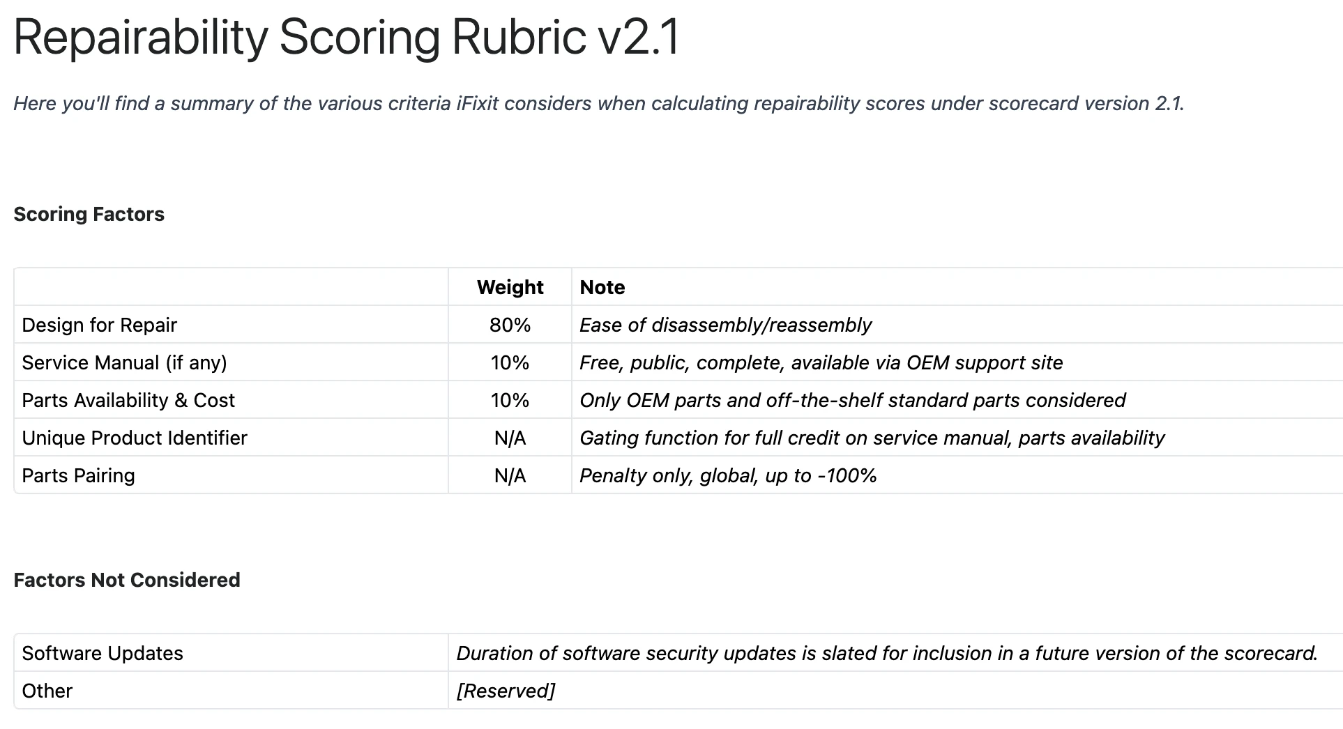
The score isn't a vibe, it's built from specific, checkable criteria: can the battery be replaced without a heat gun and specialised tools, does opening the case destroy it, are screens and other high-failure parts independently replaceable, are the screws standard or proprietary. Devices built for disassembly, the Fairphone mentioned above, or Framework's modular laptops, routinely score 9 or 10. Devices with glued-in batteries and fused components have scored as low as 0. iFixit publishes every teardown for free specifically to put that number in front of a customer before they buy, turning a hidden manufacturing decision into a visible, comparison-shoppable one, and uses the same data to lobby lawmakers directly for Right to Repair legislation.